
Edit a graphic fixture.
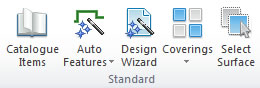
Edit Graphic Fixtures contains various controls for adjusting and shaping the graphic fixtures within the design. These tools can be accessed on the Insert tab, in the Standard group, by selecting the Auto Features list.
What do you want to do?
- Stretch the edge of a graphic fixture
- Create a single corner cut on a graphic fixture corner
- Create a convex corner curve on a graphic fixture corner
- Create a concave corner curve on a graphic fixture corner
- Create a double corner cut on a graphic fixture corner
- Split the edge of a graphic fixture
- Merge the edge of a graphic fixture
- Create a convex arc on the edge of a graphic fixture
- Create a concave arc on the edge of a graphic fixture
- Draw a freehand graphic fixture
- Automatically add joints to the graphic fixtures
- Apply a corner joint to a graphic fixture
- Apply a vertical joint to a graphic fixture
- Apply a horizontal joint to a graphic fixture
- Move a graphic fixture joint vertex
- Rotate the graphic fixture grain direction
- Link an item to a graphic fixture
- Delete a linked item from a graphic fixture
- Replace a graphic fixture with an alternative item
- Link a cut to the graphic fixture
Stretch the edge of a graphic fixture
- On the Shape tab, in the Tools group, select the Stretch Selected Edge option.
- Click one of the red handles displayed to select the edge you wish to modify.
- Drag to move the edge.
- Specify the dimension within the Information group.
- Select Apply within the Information group, or press Enter.
 TOP OF PAGE
Create a single corner cut on a graphic fixture corner
- On the Shape tab, in the Tools group, select the Single Corner Cut option.
- Click one of the red handles displayed to select the edge you wish to modify.
- Drag to move the edge.
- Specify the dimension within the Information group.
- Select Apply within the Information group, or press Enter.
Create a convex corner curve on a graphic fixture corner
- On the Shape tab, in the Tools group, select the Convex Corner Curve option.
- Click one of the red handles displayed to select the edge you wish to modify.
- Drag to move the edge.
- Specify the dimension within the Information group.
- Select Apply within the Information group, or press Enter.
Create a concave corner curve on a graphic fixture corner
- On the Shape tab, in the Tools group, select the Concave Corner Curve option.
- Click one of the red handles displayed to select the edge you wish to modify.
- Drag to move the edge.
- Specify the dimension within the Information group.
- Select Apply within the Information group, or press Enter.
Create a double corner cut on a graphic fixture corner
- On the Shape tab, in the Tools group, select the Double Corner Cut option.
- Click one of the red handles displayed to select the edge you wish to modify.
- Drag to move the edge.
- Specify the dimension within the Information group.
- Select Apply within the Information group, or press Enter.
Split the edge of a graphic fixture
- On the Shape tab, in the Tools group, select the Split Selected Edge option.
- Click one of the red handles displayed to select the edge you wish to modify.
- Drag to move the edge.
- Specify the dimension within the Information group.
- Select Apply within the Information group, or press Enter.
Merge the edge of a graphic fixture
- On the Shape tab, in the Tools group, select the Merge Selected Edge option.
- Click one of the red handles displayed to select the edge you wish to merge.
Create a convex arc on the edge of a graphic fixture
- On the Shape tab, in the Tools group, select the Convex Arc option.
- Click one of the red handles displayed to select the edge you wish to modify.
- Drag to move the edge.
- Specify the dimension within the Information group.
- Select Apply within the Information group, or press Enter.
Create a concave arc on the edge of a graphic fixture
- On the Shape tab, in the Tools group, select the Concave Arc option.
- Click one of the red handles displayed to select the edge you wish to modify.
- Drag to move the edge.
- Specify the dimension within the Information group.
- Select Apply within the Information group, or press Enter.
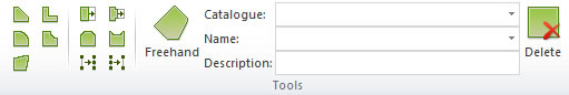
Draw a freehand graphic fixture
- On the Shape tab, in the Tools group, select the Freehand graphic fixture piece option.
- Choose the Catalogue where the freehand graphic fixture originates from.
- Choose the required graphical fixture.
- Click where you would like the first corner of your freehand graphic fixture to be.
- Continue to click at the positions for each corner.
- Complete the graphic fixture by clicking on the first corner.
NOTE Individual dimensions for the freehand graphic fixture can be specified within the Information group. If you make a mistake while creating the graphic fixture, press the delete key on the keyboard. This will delete the last point added.
Automatically add joints to the graphic fixtures
- On the Joint tab, in the Tools group, select the Auto joint graphical fixture option.
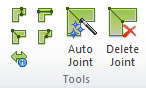
Apply a corner joint to a graphic fixture
- On the Joint tab, in the Tools group, select the Apply corner joint to graphic fixture option.
- Click one of the red handles displayed to select the joint you wish to apply.
- Click one of the white handles displayed to select the exact placement of the joint required.
- Select the Apply option.
During the jointing process, Fusion FX displays each graphic fixture in various colours indicating whether the graphic fixture can be manufactured based on its size:
- Red: The graphic fixture is too large and needs be resized or cut.
- Green: The graphic fixture is within its size limits.
- Blue: The graphic fixture is within its size limits but not recommended as optimum joint.
NOTE If any graphic fixture are too large to be manufactured (as denoted by being drawn in red) you will not be able to select Next Stage.
Apply a vertical joint to a graphic fixture
- On the Joint tab, in the Tools group, select the Apply vertical graphic fixture joint option.
- Click one of the red handles displayed to indicate the joint you wish to apply.
- Drag to move the joint.
- Specify the dimensions within the Information group.
- Select the Apply option.
During the jointing process, Fusion FX displays each graphic fixture in various colours indicating whether the graphic fixture can be manufactured based on its size:
- Red: The graphic fixture is too large and needs be resized or cut.
- Green: The graphic fixture is within its size limits.
- Blue: The graphic fixture is within its size limits but not recommended as optimum joint.
NOTE If any graphic fixture are too large to be manufactured (as denoted by being drawn in red) you will not be able to select Next Stage.
Apply a horizontal joint to a graphic fixture
- On the Joint tab, in the Tools group, select the Apply horizontal graphic fixture joint option.
- Click one of the red handles displayed to indicate the joint you wish to apply.
- Drag to move the joint.
- Specify the dimensions within the Information group.
- Select the Apply option.
During the jointing process, Fusion FX displays each graphic fixture in various colours indicating whether the graphic fixture can be manufactured based on its size:
- Red: The graphic fixture is too large and needs be resized or cut.
- Green: The graphic fixture is within its size limits.
- Blue: The graphic fixture is within its size limits but not recommended as optimum joint.
NOTE If any graphic fixture are too large to be manufactured (as denoted by being drawn in red) you will not be able to select Next Stage.
Move a graphic fixture joint vertex
- On the Joint tab, in the Tools group, select the Move Joint Vertex Position option.
- Click one of the red handles displayed to indicate the joint vertex you wish to move.
- Drag to move the vertex.
- Specify the dimensions within the Information group.
- Select the Apply option.
Rotate the graphic fixture grain direction
- On the Joint tab, in the Tools group, select the Rotate Graphic Fixture Grain Direction option.
- Click the centre of the arrow displayed against the required graphic fixture to rotate the grain direction.
- Select the Apply option.
Link an item to a graphic fixture
- On the Link tab, in the Tools group, select the Link Mode option.
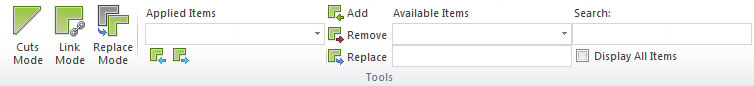
- Select the required item from the Available Links list.
- Select the Add option.
Delete a linked item from a graphic fixture
- On the Link tab, in the Tools group, select the Link Mode option.
- Select the required item from the Applied Links list.
- Select the Delete option.
Replace a graphic fixture with an alternative item
- On the Link tab, in the Tools group, select the Replace Mode option.
- Select the required item from the Available Links list.
- Select the Replace option.
NOTE The current selected item will be replaced.